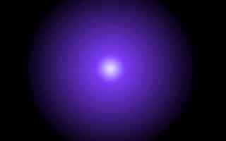
| Phong Mapping Effect [320x200x256] | Ander Haglund | 20.10.96 |
Эффект плавного затенения по Фонгу,
похожий на высвечивание фонариком части изображения. |  2k | |
| ||
| Phong Mapping Effect [320x200x256] | Ander Haglund | 20.10.96 |
Эффект плавного затенения по Фонгу,
похожий на высвечивание фонариком части изображения. | 2k | |
| ||
 {Phongmapping by Ander Haglund}
{I'll try to explain. This is a method that I think is called
phongmapping.
First you need a "real" texture mapper. With real I mean that you must
be able to use any U and V value for every corner, not just the whole
texture. Just so you know: U and V is X and Y in "texture space" so
there are no missunderstandings.
Then you make calculate a phongmap. It should look like a lot of
circles going from black in to the object color to white.
Something like this:
00000111100000
00112233221100
01234455443210
12345677654321
12345677654321
01234455443210
00112233221100
00000111100000
Where 0-5 is black to object color and 6-7 is object color to white.
I use a phongmap that is 256*256 beacuse it's easy to use with the
texture-mapper and it's 64kb (65536 bytes).
Of course you should use more than just 7 colors in the phongmap...
Now, how do we calculate the texture? It's simple! Just scan trough
the texture and check the length to the center of the texture.
A short example, this is using a palette that's 128 colors.
}
uses crt;
const palwhite = 20; {How many of the 128 colors that should be white}
var phongmap : pointer;
x,y : integer;
c,i : byte;
procedure setpal(c,r,g,b : byte);assembler;
asm mov dx,3C8h;mov al,c;out dx,al;inc dx;mov al,r;out dx,al;mov al,g
out dx,al;mov al,b;out dx,al;end;
procedure makepal(objr,objg,objb : byte);
begin
{black to object color}
for i := 0 to 127-palwhite do
setpal(i,(objr*i) div (127-palwhite),(objg*i) div (127-palwhite),
(objb*i) div (127-palwhite));
{object color to white}
for i := 0 to palwhite do
setpal(i+127-palwhite,objr+((63-objr)*i) div palwhite,
objg+((63-objg)*i) div palwhite,objb+((63-objb)*i) div palwhite);
end;
function length(x1,y1,x2,y2 : longint) : word;
begin
length := round(sqrt((x1-x2)*(x1-x2)+(y1-y2)*(y1-y2)));
end;
begin
write('Calculating...');
getmem(phongmap,65535);
for y := 0 to 127 do
for x := 0 to 127 do begin
c := length(x,y,128,128); {Get length}
if c > 127 then c := 127;
c := 127-c; {Revert the color so you don't get black in the middle}
mem[seg(phongmap^):y shl 8+x] := c;
mem[seg(phongmap^):(255-y) shl 8+x] := c;
mem[seg(phongmap^):y shl 8+(255-x)] := c;
mem[seg(phongmap^):(255-y) shl 8+(255-x)] := c;
end;
asm
mov ax,13h
int 10h
end;
makepal(32,16,63); {This is going to be a blue-magenta object}
{Draw the phongmap (in scale 1:2)}
for y := 0 to 127 do
for x := 0 to 127 do
mem[$A000:x+y shl 8+y shl 6] := mem[seg(phongmap^):x shl 1+y shl 9];
repeat until keypressed;
asm
mov ax,3h
int 10h
end;
end.
When you got the phongmap and palette right you must fix some with the
object.
First you read the object from disk (No object that fits in a const
looks good with phong, you can't phongmap a cube or simular). I sugest
that you that you read a object from 3D studio, the face for example,
that's one of the objects I'm using. When you read the object you
calculate the face normals.
Like this:
const maxp = 900; {Max points}
maxpl = 900; {Max planes}
var points : array[0..maxp,0..2] of integer;
planes : array[0..maxpl,0..2] of word;
pnormals : array[0..maxpl,0..2] of integer; {Plane normals}
{It's these normals we are going to use:}
normals : array[0..maxp,0..2] of integer; {Corner or edge normals}
maxpoint,maxpoint : word; {The actual numbers of points and planes}
i,a,n : word;
rx1,ry1,rz1,rx2,ry2,rz2 : integer;
rx,ry,rz,l : real;
begin
readobject; {This one is up to you to make, I don't know how you
store your objects...}
for i := 0 to maxplane do begin
rx1 := points[planes[i,1],0]-points[planes[i,0],0];
ry1 := points[planes[i,1],1]-points[planes[i,0],1];
rz1 := points[planes[i,1],2]-points[planes[i,0],2];
rx2 := points[planes[i,2],0]-points[planes[i,0],0];
ry2 := points[planes[i,2],1]-points[planes[i,0],1];
rz2 := points[planes[i,2],2]-points[planes[i,0],2];
{Calculate plane normal (you should know this
if you made a flat shading)}
pnormals[i,0] := ry1*rz2-ry2*rz1;
pnormals[i,1] := rz1*rx2-rz2*rx1;
pnormals[i,2] := rx1*ry2-rx2*ry1;
end;
for i := 0 to maxpoint do begin
{Reset all variabels}
rx := 0;ry := 0;rz := 0;n := 0;
for a := 0 to maxplane do
{Check if point is in plane}
if (planes[a,0] = i) or (planes[a,1] = i) or (planes[a,2] = i) then
begin
{Add plane normal to corner/edge normal}
rx := rx+pnormals[a,0];
ry := ry+pnormals[a,1];
rz := rz+pnormals[a,2];
{Increase numbers of planes}
inc(n);
end;
if n > 0 then begin {n should allways be over 0, otherwise the
point isn't used at all}
rx := rx/n;ry := ry/n;rz := rz/n; {Calculate average normal
for plane}
l := sqrt(rx*rx+ry*ry+rz*rz); {Calculate length of normal}
if l = 0 then l := 1; {So you don't get divide error}
{120 is length of normal (should be 127 but then you get some
rounding errors)}
{This scales the normals so they have the same length}
normals[i,0] := round(rx/l*120);
normals[i,1] := round(ry/l*120);
normals[i,2] := round(rz/l*120);
end;
end;
end.
Then you have come to the actual drawing. First you rotate the points
as usual. Then you rotate all normals as mush as you rotated the
points. You convert the points to 2d of course but not the normals...
Then you sort the polys and the usual stuff. Then commes the drawing
of the polys. It's pretty simple actualy. You let the X and Y value
of the corners normal be U and V value to the texture-mapper.
You must add 128 to the U and V value so you draw from the center of
the phongmap. Then you just texturmap the poly using the phongmap as
texture.
This routine should look something like this:
begin
[init stuff, calculate phongmap, go to graph mode and so on.]
repeat
[Rotate points and normals, convert to 2d and sort polys.]
for i := 0 to maxplane do
{pind[i] is from the sorting routine, just so you know}
texture(
{X and Y coordinates for the first corner in the poly:}
160+newp[planes[pind[i],0],0],100+newp[planes[pind[i],0],1],
{U and V coordinates for the first corner in the poly:}
128+newn[planes[pind[i],0],0],128+newn[planes[pind[i],0],1],
{X and Y coordinates for the second corner in the poly
and so on...}
160+newp[planes[pind[i],1],0],100+newp[planes[pind[i],1],1],
128+newn[planes[pind[i],1],0],128+newn[planes[pind[i],1],1],
160+newp[planes[pind[i],2],0],100+newp[planes[pind[i],2],1],
128+newn[planes[pind[i],2],0],128+newn[planes[pind[i],2],1]);
[Retrace, display picture and clear virtual screen.]
until keypressed;
[Go back to textmode]
end;
{Phongmapping by Ander Haglund}

{I'll try to explain. This is a method that I think is called
phongmapping.
First you need a "real" texture mapper. With real I mean that you must
be able to use any U and V value for every corner, not just the whole
texture. Just so you know: U and V is X and Y in "texture space" so
there are no missunderstandings.
Then you make calculate a phongmap. It should look like a lot of
circles going from black in to the object color to white.
Something like this:

00000111100000
00112233221100
01234455443210
12345677654321
12345677654321
01234455443210
00112233221100
00000111100000

Where 0-5 is black to object color and 6-7 is object color to white.
I use a phongmap that is 256*256 beacuse it's easy to use with the
texture-mapper and it's 64kb (65536 bytes).
Of course you should use more than just 7 colors in the phongmap...
Now, how do we calculate the texture? It's simple! Just scan trough
the texture and check the length to the center of the texture.
A short example, this is using a palette that's 128 colors.
}
uses crt;
const palwhite = 20; {How many of the 128 colors that should be white}
var phongmap : pointer;
    x,y : integer;
    c,i : byte;

procedure setpal(c,r,g,b : byte);assembler;
asm mov dx,3C8h;mov al,c;out dx,al;inc dx;mov al,r;out dx,al;mov al,g
out dx,al;mov al,b;out dx,al;end;

procedure makepal(objr,objg,objb : byte);
begin
  {black to object color}
  for i := 0 to 127-palwhite do
    setpal(i,(objr*i) div (127-palwhite),(objg*i) div (127-palwhite),
      (objb*i) div (127-palwhite));
  {object color to white}
  for i := 0 to palwhite do
    setpal(i+127-palwhite,objr+((63-objr)*i) div palwhite,
      objg+((63-objg)*i) div palwhite,objb+((63-objb)*i) div palwhite);
end;

function length(x1,y1,x2,y2 : longint) : word;
begin
  length := round(sqrt((x1-x2)*(x1-x2)+(y1-y2)*(y1-y2)));
end;

begin
  write('Calculating...');
  getmem(phongmap,65535);
  for y := 0 to 127 do
  for x := 0 to 127 do begin
    c := length(x,y,128,128); {Get length}
    if c > 127 then c := 127;
    c := 127-c; {Revert the color so you don't get black in the middle}
    mem[seg(phongmap^):y shl 8+x] := c;
    mem[seg(phongmap^):(255-y) shl 8+x] := c;
    mem[seg(phongmap^):y shl 8+(255-x)] := c;
    mem[seg(phongmap^):(255-y) shl 8+(255-x)] := c;
  end;
  asm
    mov ax,13h
    int 10h
  end;
  makepal(32,16,63); {This is going to be a blue-magenta object}
  {Draw the phongmap (in scale 1:2)}
  for y := 0 to 127 do
  for x := 0 to 127 do
    mem[$A000:x+y shl 8+y shl 6] := mem[seg(phongmap^):x shl 1+y shl 9];
  repeat until keypressed;
  asm
    mov ax,3h
    int 10h
  end;
end.

When you got the phongmap and palette right you must fix some with the
object.
First you read the object from disk (No object that fits in a const
looks good with phong, you can't phongmap a cube or simular). I sugest
that you that you read a object from 3D studio, the face for example,
that's one of the objects I'm using. When you read the object you
calculate the face normals.
Like this:

const maxp = 900; {Max points}
      maxpl = 900; {Max planes}
var points : array[0..maxp,0..2] of integer;
    planes : array[0..maxpl,0..2] of word;
    pnormals : array[0..maxpl,0..2] of integer; {Plane normals}
    {It's these normals we are going to use:}
    normals : array[0..maxp,0..2] of integer; {Corner or edge normals}
    maxpoint,maxpoint : word; {The actual numbers of points and planes}
    i,a,n : word;
    rx1,ry1,rz1,rx2,ry2,rz2 : integer;
    rx,ry,rz,l : real;

begin
  readobject; {This one is up to you to make, I don't know how you
               store your objects...}
  for i := 0 to maxplane do begin
    rx1 := points[planes[i,1],0]-points[planes[i,0],0];
    ry1 := points[planes[i,1],1]-points[planes[i,0],1];
    rz1 := points[planes[i,1],2]-points[planes[i,0],2];
    rx2 := points[planes[i,2],0]-points[planes[i,0],0];
    ry2 := points[planes[i,2],1]-points[planes[i,0],1];
    rz2 := points[planes[i,2],2]-points[planes[i,0],2];
    {Calculate plane normal (you should know this
     if you made a flat shading)}
    pnormals[i,0] := ry1*rz2-ry2*rz1;
    pnormals[i,1] := rz1*rx2-rz2*rx1;
    pnormals[i,2] := rx1*ry2-rx2*ry1;
  end;
  for i := 0 to maxpoint do begin
    {Reset all variabels}
    rx := 0;ry := 0;rz := 0;n := 0;
    for a := 0 to maxplane do
      {Check if point is in plane}
      if (planes[a,0] = i) or (planes[a,1] = i) or (planes[a,2] = i) then
      begin
        {Add plane normal to corner/edge normal}
        rx := rx+pnormals[a,0];
        ry := ry+pnormals[a,1];
        rz := rz+pnormals[a,2];
        {Increase numbers of planes}
        inc(n);
      end;
    if n > 0 then begin {n should allways be over 0, otherwise the
                         point isn't used at all}
      rx := rx/n;ry := ry/n;rz := rz/n; {Calculate average normal
                                         for plane}
      l := sqrt(rx*rx+ry*ry+rz*rz); {Calculate length of normal}
      if l = 0 then l := 1; {So you don't get divide error}
{120 is length of normal (should be 127 but then you get some
 rounding errors)}
      {This scales the normals so they have the same length}
      normals[i,0] := round(rx/l*120);
      normals[i,1] := round(ry/l*120);
      normals[i,2] := round(rz/l*120);
    end;
  end;
end.

Then you have come to the actual drawing. First you rotate the points
as usual. Then you rotate all normals as mush as you rotated the
points. You convert the points to 2d of course but not the normals...
Then you sort the polys and the usual stuff. Then commes the drawing
of the polys. It's pretty simple actualy. You let the X and Y value
of the corners normal be U and V value to the texture-mapper.
You must add 128 to the U and V value so you draw from the center of
the phongmap. Then you just texturmap the poly using the phongmap as
texture.

This routine should look something like this:

begin
  [init stuff, calculate phongmap, go to graph mode and so on.]
  repeat
    [Rotate points and normals, convert to 2d and sort polys.]
    for i := 0 to maxplane do
        {pind[i] is from the sorting routine, just so you know}
        texture(
        {X and Y coordinates for the first corner in the poly:}
        160+newp[planes[pind[i],0],0],100+newp[planes[pind[i],0],1],
        {U and V coordinates for the first corner in the poly:}
        128+newn[planes[pind[i],0],0],128+newn[planes[pind[i],0],1],
        {X and Y coordinates for the second corner in the poly
         and so on...}
        160+newp[planes[pind[i],1],0],100+newp[planes[pind[i],1],1],
        128+newn[planes[pind[i],1],0],128+newn[planes[pind[i],1],1],
        160+newp[planes[pind[i],2],0],100+newp[planes[pind[i],2],1],
        128+newn[planes[pind[i],2],0],128+newn[planes[pind[i],2],1]);
    [Retrace, display picture and clear virtual screen.]
  until keypressed;
  [Go back to textmode]
end;